Category Archives: electronics

PoelControl – Any News There?

PoelControl – ein Projekt zur Entwicklung einer elektronischen Steuerung für den automatisierten Betrieb mit Pöl – dämmerte den Winter über im Winterschlaf. Dennoch gab es einige Ergebnisse.

PoelControl I ist eine Anzeigeinstrument von Infos rund um den Pölbetrieb. Hiermit ist es möglich, alle für den Pölbetrieb relevanten Parameter wie Temperaturen, 2 Drücke (Ladedruck, Sog bzw. Druckabfall über einem Kraftstofffilter) sowie Tankpegel zu messen und anzuzeigen.

PoelControl I

Fokus der Entwicklung war hierbei eine minimale Baugröße, die nur unwesentlich größer als das eingesetzte Display ist. Dies wurde durch konsequente Verwendung von SMD-Komponenten erreicht. Der Anschluss erfolgt trotz Miniaturisierung mittels standardisierter Wannenstecker, so dass ein sicherer Kontakt gewährleistet ist.

Desweiteren ist ein Relaismodul fertig. 8 Relais (Belastbarkeit jeweils 5 A, I_total < 10 A) können über I2C gesteuert werden. Auf dem zweiten Bild sind RelaisBoard wie auch ein Board zur Meßwerterfassung gemeinsam zu sehen.

RelasiBoard

SensorBoard

Eagle Commands

Some handy commands for the PCB layout software Eagle from cadsoft.de that are not readily available via the menu buttons… you may see this as a personal reminder that these commands exist :-9

Ever wondered how to draw the name of a network or a bus next to the wire of a schema? Label is your friend. Select the <label> command, select the wire and place the text.

Some ICs are shipped with hidden power pins, something I never do in my own libraries. Here the eagle naming convention holds true that all pins of equal name are connected. To bad if you are using a different power pin naming scheme. With invoke these previously hidden power pins are shown in the schema.

Btw – objects with identical names are connected E. g. just draw short wires for SCL and SCK and name them accordingly. Then, wherever you need I2C just hook up two short wires with the sames names. Eagle will assume these wires are connected, voila! Quite handy to cleanup a convoluted and chaotic schema.

Notes and Tips for AVR

ISP connector

Space on PCBs is sparse… so, what to do with the ISP connector? See the discussion on microcontroller.net as well as the end of the Simple AVR programmers page.

C++ on Avr?

Sure, why not! But take care. E. g. about how to use C++ member funtions as interrupt handlers. Here, also see the information about Member Function Pointers and Pointers to Member functions.

Also quite interesting is the intelligent access to flash strings

IDEs and some such

Debugging in Eclipse for Avr

Personal note – Debuging von Amel AVRs unter Linux aus Eclipse

Quelle: mikrocontroller.net; Thread: Eclipse und WinAVR:

 1.) simulavr von Konsole starten:
     >> simulavr -g -p 1212 -d atmega8 -P simulavr-disp

 2.) Eclipse
     Debug-->C/C++ Local Application
       Main:
         Projekt: AVR-Test (oder wie auch immer)
         C/C++ Application: Debug/AVR-Test.elf
       Debugger:
         Debugger: gdbserver Debugger
         Main:
           GDB debugger: avr-gdb
           GDB command file: gdbinit (ist angehängt)
         Connection:
           Type: TCP
           Hostname or IP: localhost
           Portnumber: 1212

Weitere Infos hier und hier

AVR Modules

Hier eine kleine Gallerie von Modulen für die elektronische Steuerung für den Pflanzenölbetrieb.

Die ersten drei Module sind ein Mainboard-Adapter für ein das Mega168 Mini Modul von emebedit.de sowie eine Speicherkarte und eine Grundplatine für das DOG-M-Display.

Die beiden letzten Module dienen zur Erfassung von Messwerten sowie zur Ansteuerung von Verbrauchern über Relais.

Module

Module

Module

Großversionen der Bilder sind hier zu finden.

Avr code size optimization revisited

Code size optimization is important. Especially on microcontrollers with their strict memory limitations. In my last post I wrote about optimization methods for WinAvr and GCC.

With the new release of WinAvr WinAvr 20070525 now includes GCC 4.x and an updated avr-libc 1.4.6. Therefore most of the steps described in my previous post are no longer required.

Simply adding:

  • CFLAGS += -ffunction-sections
  • LDFLAGS += -Wl,–gc-sections

to your custom makefile (no idea how to integrate this into a managed make project) will analyze your code. Methods that are not used in the project are not linked into the final binary.

I like to have versatile libraries for peripherals or other taks with many convenience methods for comfortable coding. Yet, normally only a rather small selection of these methods is used. With the linker and compiler options from above a significant reduction in byte size is achieved. In one project the binary size dropped by about 30 – 40 %.

AVR: Code size optimization

Ever wondered why your binary code on the avr is quite big with next to no functions used? This is due to gcc 3.x that links / adds all your functions and relevant includes to the final binary even if some functions are never called. With gcc 4.x unused functions can be removed by the linker.

For more information see this thread on AvrFreaks.

The executive summary:

  • Start from a clean current WinAvr installation
  • Extract gcc 4.11 from AtmanAvr into this directory
  • Extract the recent avr-libc 1.4.5 into this directory
  • Adapt your Linker and Compiler flags accordingly. Add: CFLAGS += -ffunction-sections and LDFLAGS += -Wl,–gc-sections
  • That’s it!

Unfortunalty, this does not work for member functions of classes. So, if you are one of the rare persons developing in C++ for AVR this still does not help 🙁 Back to using IFDEFs again…

Nevertheless, on my projects C++ constructs are only used in special situations like RingBuffer, FiFo etc. Plain C code is optimized and unused functions are removed even if the code is compiled as C++.

Dog-M Display in Eagle3D

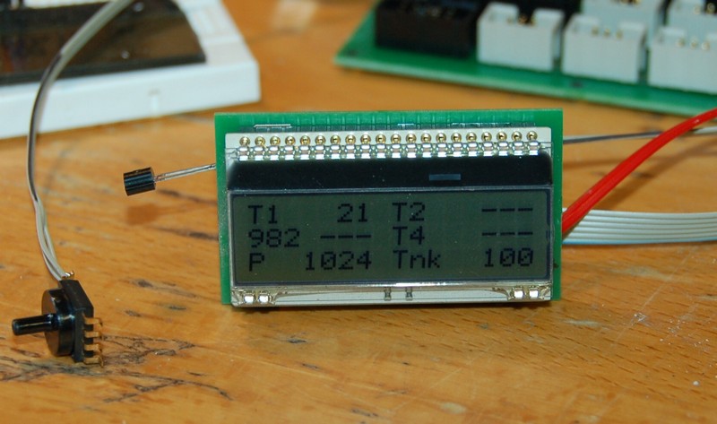
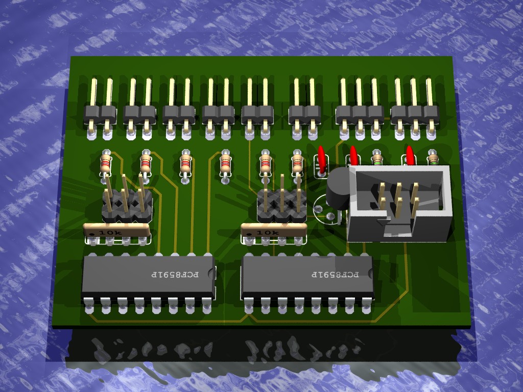
Mit Hilfe von Eagle3D kann für eine Leiterplatte eine 3D-Ansicht generiert werden. Leider ist bei der aktuellen Version kein Bauteil für das Dog-M Display vorhanden.

Hier also eine Definition für das DOG-M Display für Eagle3D.


dogDisplay

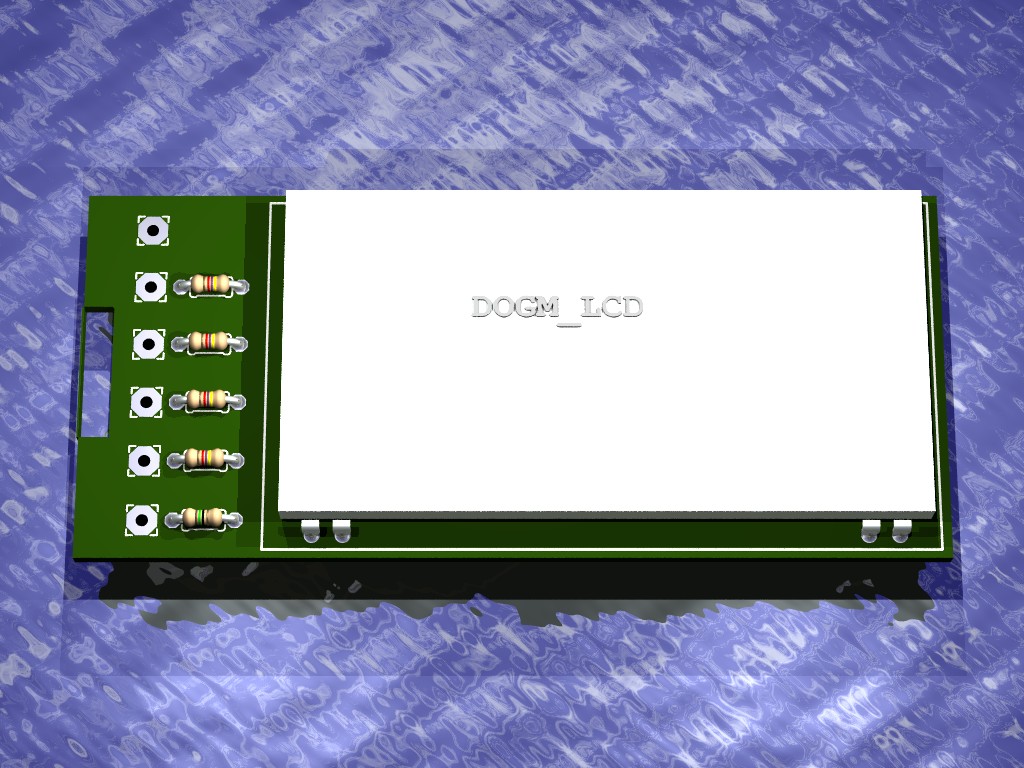
Zur Installation muss unten stehende Definition in user.inc eingefügt werden:

 #include "connector.inc" 

 #macro DISPLAY_DOGM(value)
 union{
  // upper pin row
  object{IC_DIS_PIN() rotate<0,180,0> translate<0,-3.75,0>}
  object{IC_DIS_PIN() rotate<0,180,0> translate<2.54,-3.75,0>}
  object{IC_DIS_PIN() rotate<0,180,0> translate<5.08,-3.75,0>}
  object{IC_DIS_PIN() rotate<0,180,0> translate<7.62,-3.75,0>}
  object{IC_DIS_PIN() rotate<0,180,0> translate<10.16,-3.75,0>}
  object{IC_DIS_PIN() rotate<0,180,0> translate<12.700,-3.75,0>}
  object{IC_DIS_PIN() rotate<0,180,0> translate<15.240,-3.75,0>}
  object{IC_DIS_PIN() rotate<0,180,0> translate<17.780,-3.75,0>}
  object{IC_DIS_PIN() rotate<0,180,0> translate<20.320,-3.75,0>}
  object{IC_DIS_PIN() rotate<0,180,0> translate<22.860,-3.75,0>}
  object{IC_DIS_PIN() rotate<0,180,0> translate<25.400,-3.75,0>}
  object{IC_DIS_PIN() rotate<0,180,0> translate<27.940,-3.75,0>}
  object{IC_DIS_PIN() rotate<0,180,0> translate<30.480,-3.75,0>}
  object{IC_DIS_PIN() rotate<0,180,0> translate<33.020,-3.75,0>}
  object{IC_DIS_PIN() rotate<0,180,0> translate<35.560,-3.75,0>}
  object{IC_DIS_PIN() rotate<0,180,0> translate<38.100,-3.75,0>}
  object{IC_DIS_PIN() rotate<0,180,0> translate<40.640,-3.75,0>}
  object{IC_DIS_PIN() rotate<0,180,0> translate<43.180,-3.75,0>}
  object{IC_DIS_PIN() rotate<0,180,0> translate<45.720,-3.75,0>}
  object{IC_DIS_PIN() rotate<0,180,0> translate<48.260,-3.75,0>}
  // lower pin row
  object{IC_DIS_PIN() rotate<0,0,0> translate<0,-3.75,-27.940>}
  object{IC_DIS_PIN() rotate<0,0,0> translate<2.54,-3.75,-27.940>}
  object{IC_DIS_PIN() rotate<0,0,0> translate<45.72,-3.75,-27.940>}
  object{IC_DIS_PIN() rotate<0,0,0> translate<48.260,-3.75,-27.940>}

  // display case
  box {<-2.54,0.5,1.27>,<50.8,3,-26.67> texture{col_silver}}

  // text on display
  box {<-2.54,0.5,1.27>,<50.8,3,-26.67> pigment{White}}
  text {ttf besch_font value 0.2, 0 pigment { Gray60 } rotate <90,0,0> scale<3,1,3> translate<13.1,3.21,-10>}

  // translate part
  translate<-26.67,0,16.51>
 }
 #end

PoelControl – Modularisierung und Module

Ein neuer Ansatz für eine elektronische Steuerung. Hier also die ersten Module für eine modular ausgelegte Steuerung.

Vor einiger Zeit wurde bereit ein versuch gestartet, eine microcontrolergesteuerte Lösung zur Erfassung von Messwerten zu entwickeln. Diese Loesung funktionierte zwar, eine spätere Erweiterung wie auch das Platinenlayout waren alles andere als einfach und optimal.

Daher wurde ein neuer Ansatz entwickelt. Eine kommerziell erhältliche Hauptplatine ist hier zentraler Bestandteil der Steuerung. Der dort verbaute Microcontroller liest Messwerte aus, zeigt diese an, reagiert auf Nutzereingaben und steuert Ventile etc. Die eigentlichen Pölfunktionen werden durch selbstentwickelte Module bereitgestellt.

In einem ersten Schritt wurden Module für die Datenerfassung, -speicherung und -anzeige entwickelt. Diese gehen die Tage in die Fertigung. Was wird gebaut?

Module

Datenerfassung

Ohne Datenerfassung kann keine Steuerung funktionieren. Dieses Modul kann bis zu 5 Temperaturmesswerte, 2 Druckmesswerte und den Tankpegel erfassen und an die Hauptplatine weiterleiten.

DataInput

Anzeige

Zur Anzeige kommt Display mit 3 * 16 Zeichen zum Einsatz.


Display

Datenspeicherung

Ein EEPROM Baustein kann verwendet werden, um Messwerte bzw. weitergehende Konfigurationseinstellungen zu speichern.

Probleme und Überlegungen

Für die Kommunikation zwischen Erweiterungsmodul und Hauptplatine kommen I2C und SPI zum Einsatz. Die Erfahrung wird zeigen, ob insbesondere im Motorraum I2C betriebssicher funktioniert. Hier sind mir unterschiedliche Infos bekannt.

Sollte es zu Störungen kommen, so kann eventuell über abgeschirmte Kabel, CRC-Prüfungen etc. eine Lösung geschaffen werden. Klappt auch dies nicht, so wird wohl oder übel der Weg hin zu einem anderen Bus-System wie RS485 oder CAN notwendig sein. Abwarten und hoffen …